Revit for MEP: what the mechanical, electrical and plumbing tools cover
Full Revit models duct, pipe and circuit systems; Revit LT isn't meant to. Pick the product, set up the template and link, then trace one air terminal.
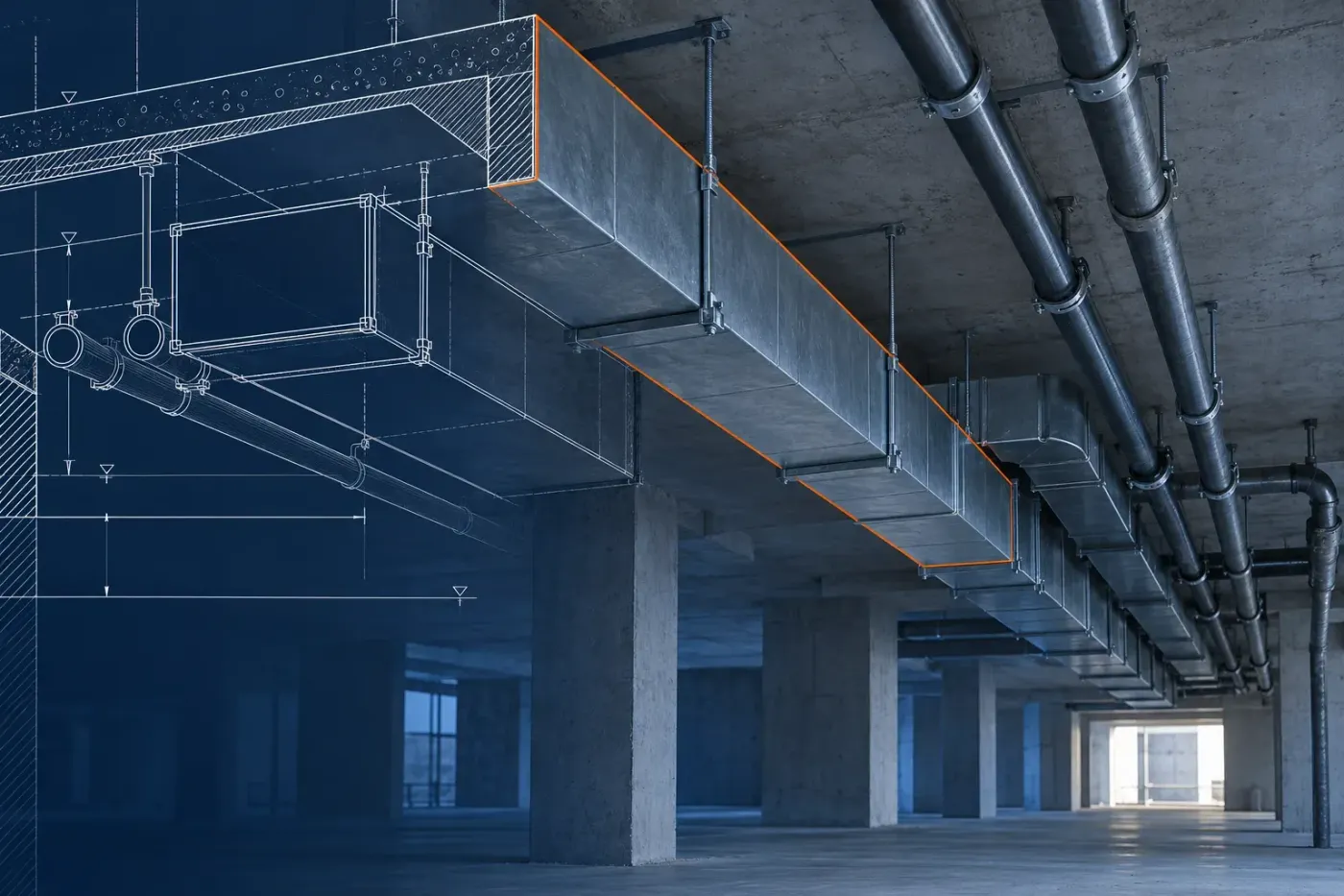
Revit MEP software means the building-services tools in full Autodesk Revit. You can model duct and pipe networks or create electrical circuits with their connected components. Revit LT is not intended for MEP modeling, so choose full Revit when your project needs those systems.
Once the project is set up, follow one model element, such as an air terminal: identify its system membership, then examine how it appears in the project views. The workflows below use Autodesk's English Revit 2027 Help.
Choose the product before the template
Revit MEP is a former product name. Autodesk's announcement of Revit 2017 says that with this release it discontinued the separate Revit Architecture, Revit Structure and Revit MEP products and replaced them with one Revit that includes all their functions. Revit 2017 shipped in April 2016, so the release number runs a year ahead of the calendar. An older course using the name Revit MEP does not establish that you need a separate current MEP edition.
- Full Revit: choose it to create MEP systems within a Revit building model. Autodesk's MEP documentation covers mechanical, electrical and piping systems, spaces and system inspection.
- Revit LT: keep its architectural scope in mind. A different project template does not remove the edition restriction. Check the wider Revit LT limits before choosing it for a multidisciplinary assignment.
- AutoCAD MEP: this belongs to the AutoCAD product family. Autodesk lists the MEP toolset as included with AutoCAD; it is a different application route from Revit. Owning AutoCAD MEP does not produce Revit deliverables; when a project asks for them, settle the product and the file workflow first.
Full Revit is paid software, with subscription and Flex access presented on Autodesk's Revit purchase page, which also directs eligible students to Education verification. There is no separate current Revit MEP price to add to a full Revit license.
Check the workstation too: Autodesk's 2027 requirements specify Windows 11, and the Apple-computer configuration they describe runs Windows in Parallels Desktop.
What the MEP tools cover
Mechanical: equipment, air terminals and ducts
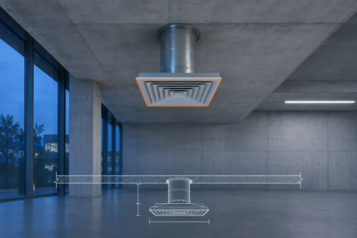
The mechanical tools place air terminals and mechanical equipment. They also create ductwork, with fittings or accessories where required. Supply, return and exhaust systems are documented starting points. Routing and sizing tools work with the system information you give the model.
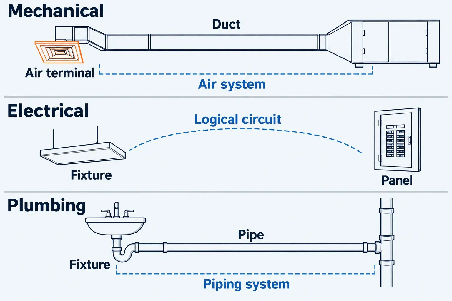
A duct system has a logical side as well as a physical route. Revit's duct-system guidance describes assigning terminals and equipment to a system, then laying out ductwork, or creating system membership as ductwork connects the components. It also identifies the System Browser as the place to check whether components belong to the correct system.
Electrical: components, circuits and panels
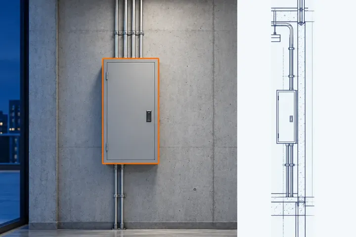
Revit's electrical tools place devices or lighting fixtures, then connect components through circuits. Electrical equipment and panel schedules carry the circuit information into the design documentation. For physical routes, Revit provides wire tools as well as cable tray and conduit.
For a power circuit, a component needs an available connector and compatible distribution information, including voltage and number of poles. Creating a circuit does not require drawing wire runs. Visible wiring and electrical system membership therefore answer different questions. The separate guide to electrical circuits follows that relationship into the panel.
Plumbing and piping: fixtures, systems and pipe routes
The plumbing-system documentation covers domestic hot water, domestic cold water and sanitary systems connecting fixtures. The logical system is independent of the piping used to show its route and connections. For sanitary systems, Autodesk's workflow calls for sloped piping because the flow depends on gravity.
Piping also extends beyond plumbing fixtures: Autodesk's piping design workflow names applications such as hydronic heating. It moves from equipment and system assignment to piping, routing, sizing and connectivity checks. The engineer still has to establish the design requirements that make those operations meaningful.
Start with a template and an architectural link
For a coordinated project, begin with the agreed Revit release, the architectural model and a suitable MEP project template. Protect the original model files before any upgrade: Autodesk's MEP setup guidance warns that a model created or modified in a newer release cannot later be opened in an older one. Do this setup in full Revit, because Revit LT, in general, can't use the Copy/Monitor tools that step 3 relies on.
- Create your MEP project from a template. Use your CAD/BIM manager's template where one is supplied. It carries discipline settings into the new project. In the documented New Project workflow, select a Template file or Browse to an RTE, choose Project under Create new, then confirm with OK. A particular template name is not a separate software edition.
- Link the architectural model. The documented setup uses a new MEP model linked to the architectural model, so the building geometry provides context while the engineering model contains its design. Agree the model alignment with the project team before laying out systems.
- Establish corresponding levels and monitor the relevant changes. Autodesk's setup includes host-project levels corresponding to the link and Copy/Monitor to recognize linked-model changes. This coordination is a project setup task, not a benefit obtained just by drawing a duct.
- Prepare the views and spaces your task requires. Mechanical views need a suitable discipline and view range. If spaces should use the architectural boundaries, Autodesk's linked-model workflow turns on Room Bounding for the link before placing spaces in the MEP model.
Check the link alignment and the views before placing components. Build the required systems, verify connectivity, then prepare the drawings.
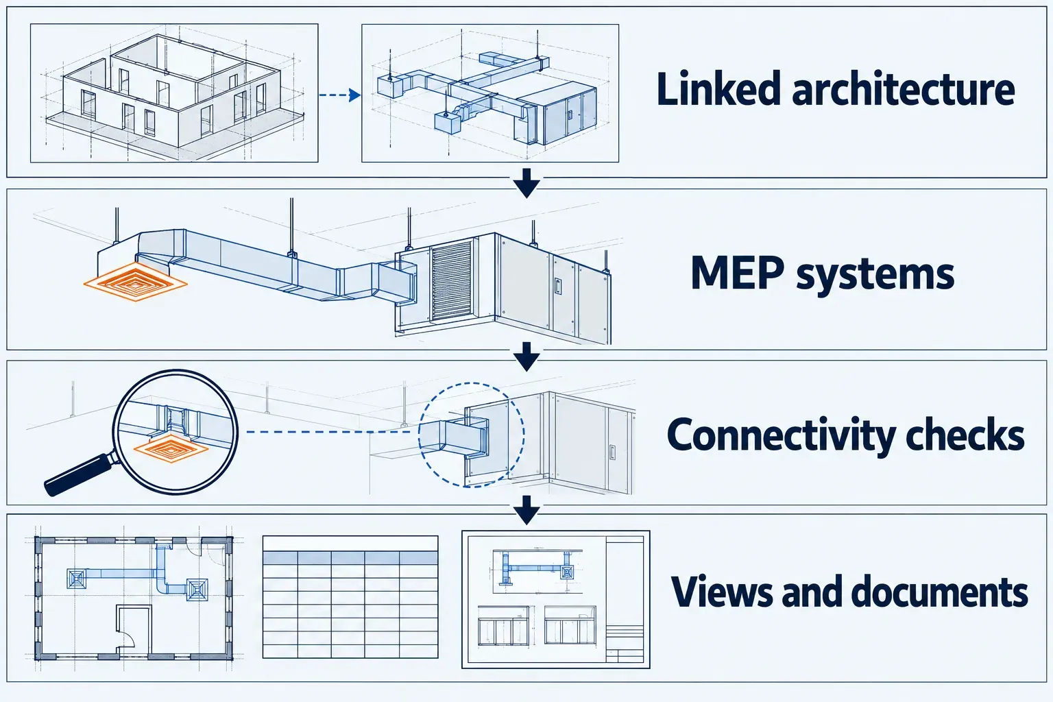
Follow one air terminal into the documentation
Consider an educational example: a supply-air terminal above a room. It starts as a placed component, joins a supply-air system and connects to ductwork. Autodesk's duct design sequence then calls for checking connectivity and inspecting system flows. Seeing a terminal beside a duct in 3D is not enough to establish those relationships.
Within its category, a family contains types; placing a terminal of a chosen type creates an instance. Changing a type property affects every instance of that type, while an instance-property edit affects the selected elements. The check below follows the placed terminal's system membership; the plan's discipline and view range control the view you inspect it in.
The same component can appear in a plan, a section and the project's scheduled information. Autodesk describes views, sheets and schedules as presentations of the same building model. A model change can coordinate across these representations, while the designer chooses which views and information each document shows.
I'd check system membership before view appearance, because a component can look correctly placed while it is still unassigned. The System Browser provides the component and system hierarchy for that check.
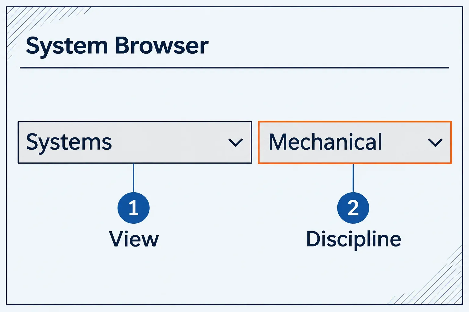
- Open the browser. Click View > Windows > User Interface drop-down > System Browser, or press F9.
- Choose the scope. In the browser's View bar, choose Systems, then Mechanical to inspect mechanical components.
- Find the component. Expand the relevant system or Unassigned folder. Right-click the component and choose Select to highlight it in the current view, or Show to open a view containing it. If it is unassigned, inspect its system assignment before relying on the drawing.
Then locate the terminal in a section or mechanical plan. When the model relationship is right, tag air terminals to communicate the required information on the drawing.
Where the tools stop
Choose full Revit when the assignment needs connected MEP elements and Revit model documentation. Then assess specialist requirements separately. For example, MagiCAD offers discipline-specific modeling and calculation tools within Revit. A package built for Revit has its own scope; its feature list is not a list of everything included in base Revit.
A modeled connection, a sizing result or a tidy sheet does not by itself establish a safe, approved engineering design. Treat calculations as dependent on the model inputs and the applicable engineering method, and keep equipment selection and code decisions with the responsible designer. When the next task is a power circuit, Revit electrical basics runs it from the panel and devices to the panel schedule; the other structure and MEP tasks are in the Structure & MEP guides.