Revit electrical basics: panels, circuits and fixtures
Link the architect's model, check electrical definitions, then follow one circuit from placed devices to its panel and schedule. Wire graphics stay optional.
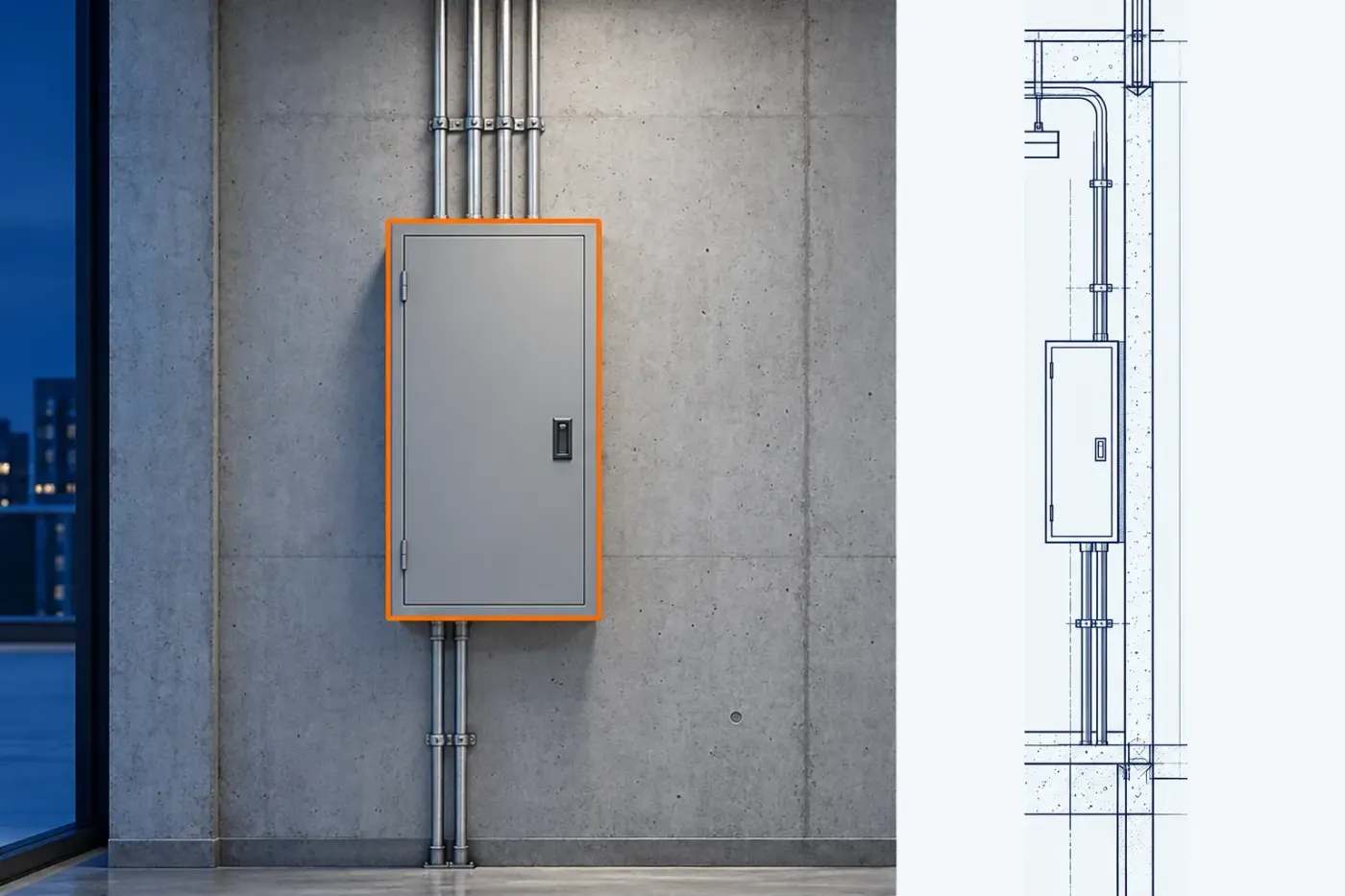
To model electrical work in Revit, check the project's electrical definitions, place the panel and the devices or lighting fixtures, then create a power circuit from the devices and assign it to the panel. A panel schedule and Check Circuits then show whether the circuit reached that panel; wire graphics are optional. Voltages, poles and load values come from the project's engineer and the applicable codes, because Revit checks connectivity, not the design.
This route follows full Revit 2027; Revit LT doesn't support MEP modeling, and Autodesk's Revit LT overview lists electrical engineering modeling among the things LT isn't intended for.
Start from an electrical-ready project and the linked architecture
Before step 1, have three things in place: a project, the architect's walls and ceilings, and the families that will sit on them.
- Project. Start it with File tab, New, Project and pick the template that fits electrical or systems work under Template file in the New Project dialog, or your office's template if it already carries the electrical settings and views.
- Architecture. Link the architect's model with Insert tab, Link panel, Link Revit. In the Link Revit procedure, Auto - Origin to Origin fits most pairs of models, and Auto - By Shared Coordinates applies when your model uses shared coordinates. If the linked walls don't show, set the view's Discipline to Coordination, then halftone the linked model so your devices read over it.
- Families. Check that the available component families include the panel, the devices and the fixtures you need. Against a linked model, pick face-based versions: Autodesk converts host-based fixtures copied out of a link with Copy/Monitor into face-based ones because that makes them easier to host on surfaces in linked models.
When you place a face-based family, the ribbon shows a Placement panel with three placement options: Place on Vertical Face (only some components offer it), Place on Face for a face at any angle, such as a linked wall or ceiling, and Place on Work Plane when the view has an active work plane. Revit selects the option you used last.
Check what the electrical definitions will affect
Open Manage tab, Settings panel, MEP Settings, Electrical Settings. These project settings hold voltage definitions, distribution systems, wiring, load calculations and circuit naming. Set them before the first circuit, because every panel picks its distribution system from these lists.
| Set it here | It reaches | Check before circuiting |
|---|---|---|
| Voltage and distribution definitions | The project's available electrical definitions | Phase, configuration, wires and line-to-line or line-to-ground voltages match the design. |
| Distribution System on a panel | The selected equipment instance | An already-defined system is compatible with that panel's voltage. |
| Load classification and demand factors | Connector classifications and associated demand estimates | Classifications and factors follow the project's engineering requirements. |
A change here reaches every panel that draws on these definitions. Revit doesn't stop voltage values that can't physically exist, so a definition the dialog accepts can still be wrong.
Load classifications belong to electrical connectors, and demand factors are assigned to classifications. Their demand calculation role shows up in panel properties and schedules, so factors carried over from a sample project would travel straight into this panel's estimated demand.
Place the panel, then the devices or lighting fixtures
Open the floor plan where the panel goes, with the linked walls and ceilings visible. The device and lighting fixture tools preview the family as the cursor moves over a valid host or location, which is the quickest sign that a hosted family can attach there.
- For the panel, click Systems tab, Electrical panel, Electrical Equipment. Pick the equipment type in the Type Selector, move over a valid host or location and click to place it. Leave Tag on Placement selected on the ribbon if the plan needs the tag.
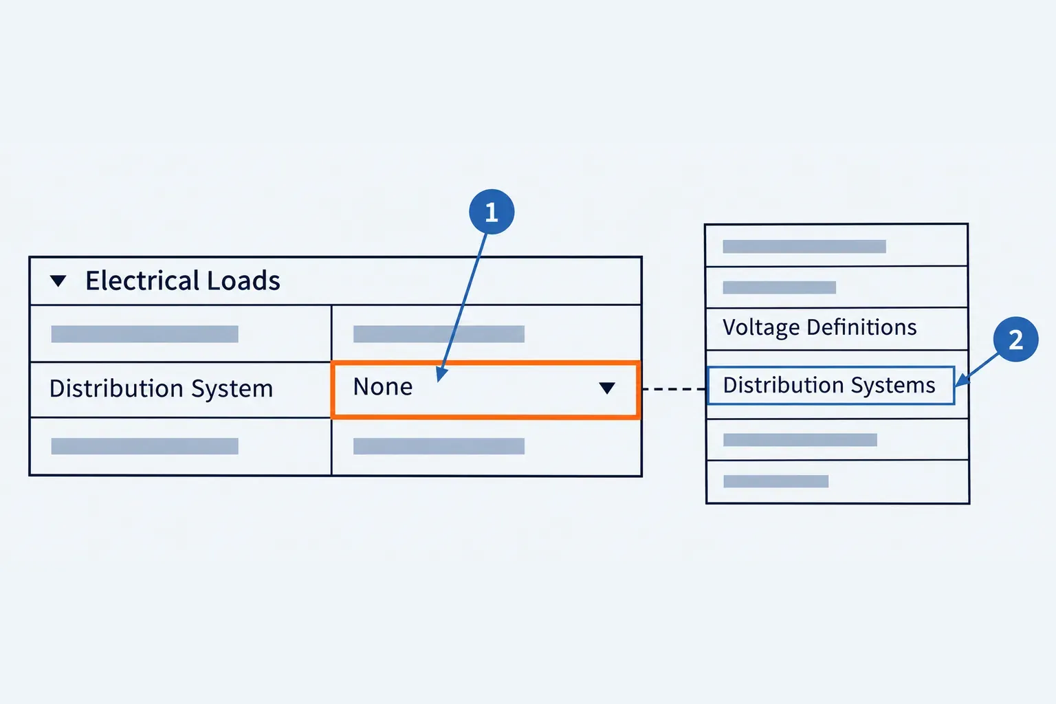
- Select the panel and open Distribution System under Electrical Loads in the Properties palette. Choose one of the systems already defined in Electrical Settings; when only one applies, Revit assigns it automatically.
- For a device, click Systems tab, Electrical panel, Device, choose the device kind and then its type in the Type Selector. Click a valid host or location, then click Modify to end placement.
- For a lighting fixture, use Systems tab, Electrical panel, Lighting Fixture. Choose the fixture type, place it on its ceiling or wall and click Modify.
A panel has to be configured for a distribution system before it can be used with circuits, and its list shows only the defined systems that match the panel's voltage. If the list offers nothing but None, compare the voltage definitions and distribution systems in Electrical Settings with the panel family's connector. Autodesk's missing-panel troubleshooting names two causes: a connector that's missing or lacks the right voltage or number of poles, and no distribution system that matches the connector's values.
Create one circuit and assign its panel
Start with the devices or fixtures for one intended circuit. The power and lighting circuit procedure builds a logical connection first; wire graphics are a separate step.
- Select one or more electrical devices or lighting fixtures that belong on the same circuit.
- On the Modify | Electrical Fixtures or Modify | Lighting Fixtures tab, click Create Systems panel, Power.
- If Specify Circuit Information appears, enter the circuit's specified voltage and number of poles, then click OK.
- With the circuit selected, use Modify | Electrical Circuits tab, System Tools panel. Choose the panel or transformer in the Panel drop-down, or type its name in Search.
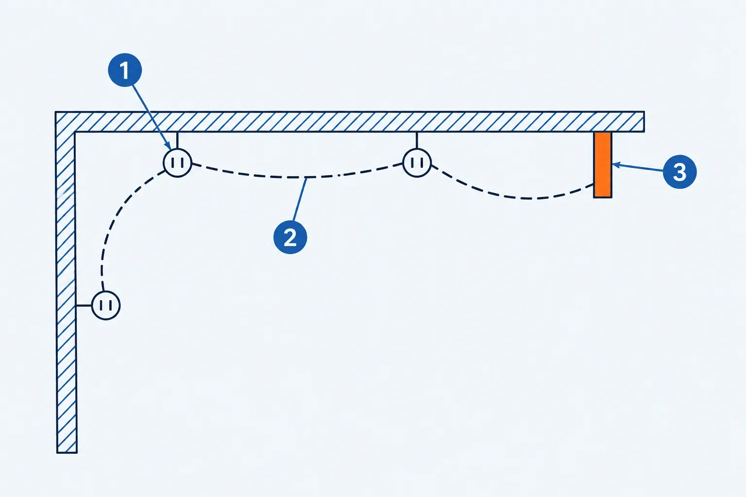
The selected circuit shows as dashed lines between its components, a temporary stand-in for wiring. The Panel list puts the current panel at the top and the three most recently used panels at the bottom, and that recent list is filtered by connector classification, voltage and poles. A panel still showing None for Distribution System can't take the circuit, so fix that first.
If the chosen panel has no unassigned slots but has spares or spaces that aren't locked, Revit prompts you to replace a spare or space with the circuit. Check which slot it took in the panel schedule afterward.
Keep wire graphics separate from the logical circuit
Permanent wiring is optional, and Revit keeps the circuit's information without it. I'd keep the circuit logical until a sheet needs wire graphics, because the circuit data doesn't depend on them. Permanent wires, once drawn, stay visible in the view even when the circuit isn't selected.
When the sheet does need them, highlight one of the circuit's components, press Tab until the circuit highlights, and click. The generate wiring controls in the view, or the Convert to Wire panel on the Modify | Electrical Circuits tab, draw arc or chamfered wiring and add the home run to the panel automatically. The permanent-wiring procedure covers both, plus Add Wire on the Systems tab's Electrical panel for wire drawn by hand.
Create the panel schedule and inspect the connection warnings
Check the circuit somewhere other than the plan where you made it. The panel schedule lists the panel's circuits and its load summary according to its template, so a missing row points straight at the assignment.
- Select one panel, or several panels of the same type, in the drawing area.
- Click Modify | Electrical Equipment tab, Electrical panel, Create Panel Schedules. Choose the default template or the option to choose a template.
- Find the circuit's row in the schedule that opens. The schedule stays under Panel Schedules in the Project Browser.
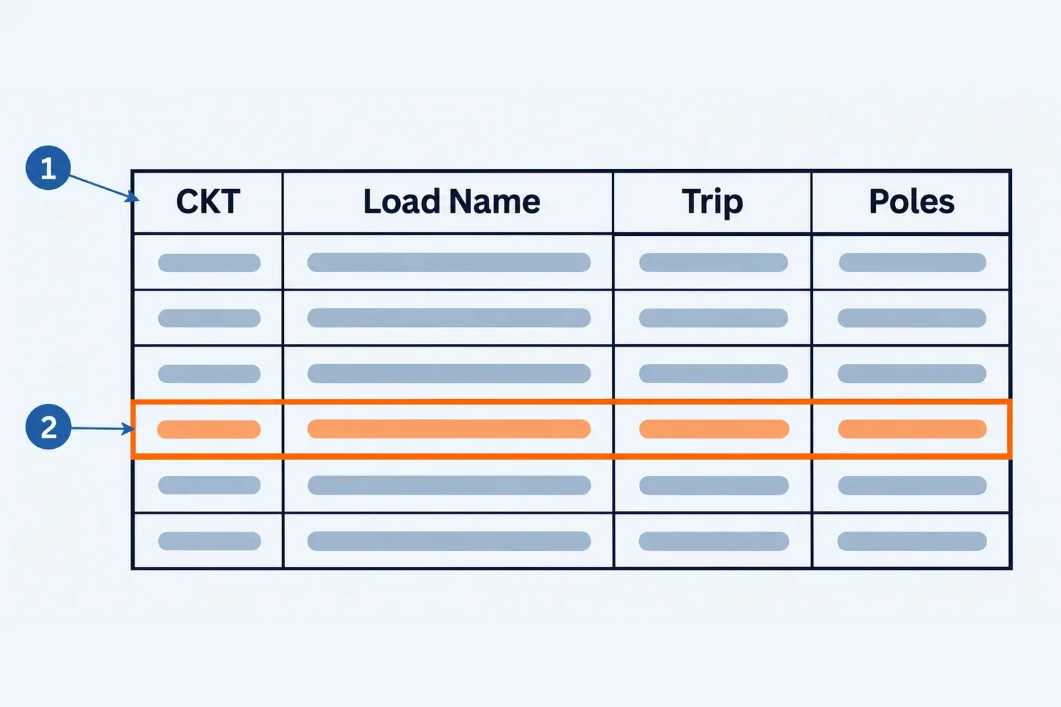
For several schedules at once, use Analyze tab, Reports & Schedules panel, Panel Schedules, select the panels in the dialog and click OK. The panel-schedule creation procedure also explains why the contextual command isn't available when the selected panels have different types.
Then click Analyze tab, MEP Connections panel, Check Circuits. If warnings appear, expand them, select an affected device and click Show to highlight it. Correct the connection and run the circuit connection check again until no warnings remain.
This route ends at one circuit on one panel, and it stops in Revit LT. If a wall-hosted family won't attach to the architect's linked walls, go back to the start state and use its face-based version. For where electrical sits among the other systems disciplines, continue with MEP in Revit.