How to create a Revit family from a template
Build a small metric furniture block from reference planes, give it two width types, then check the RFA in a test project. Template recovery and reporting limits are covered where they matter.
Start a loadable Revit family with File tab, New, Family, then choose a template for the hosting the component needs. Build reference planes, label their dimensions as parameters and flex that framework before adding geometry. Save the finished RFA and load it into a test project to check the placed component.
This example follows English Revit 2027 on Windows and makes a simple metric furniture block with two widths. It's a first parametric form, ready for further detail. For the choice between loadable, system and in-place content, use the three kinds of Revit families.
Choose the host and the reach of each size first
Keep a test project open in the same Revit session. Load into Project needs an open receiving project, and the test model keeps unfinished content out of the job.
The family template determines its hosting and behavior. Use a standalone template for this freestanding block. A wall-based or face-based template solves a different placement task; specialty templates can also restrict which category they support. The Structural Framing template, for example, is specifically for structural framing content.
I'd use type parameters for the block's widths because a type edit reaches every current and future instance of that size. Use instance parameters for values that vary between placements. When editing in a project, an instance edit applies to the selected elements, so check whether one or several are selected.
| Set it here | It reaches | Choose it when |
|---|---|---|
| A type parameter | All instances of that family type | The component comes in named sizes |
| An instance parameter | The selected placed instance or instances | The value varies by placement |
Decide about reporting separately. The ordinary family parameters used below control geometry and appear in project Type Properties. A custom parameter that must appear in a schedule or tag needs a shared definition. A successful furniture tag doesn't prove that a custom Width parameter can be reported.
Revit LT also provides standalone and host-based family templates. Its template selection is narrower than full Revit's, so check the LT list before choosing a specialty workflow.
1. Open a metric template and set the category
- Choose File tab, New, Family. In New Family - Select Template File, browse the installed metric templates and select Metric Generic Model.rft for this example. This file name is also used in Autodesk's 2027 family-creation instructions.
- Click Open. The template opens in the Family Editor, with reference planes and the views supplied by that template.
- Choose Create tab, Properties panel, Family Category and Parameters. Select Furniture for this example and click OK. Use a category available to the chosen template; changing category isn't a way around a specialty template's restrictions.
- Choose File tab, Save As, Family. Give the RFA a descriptive name and save it in a working folder. Keep it out of the shared library until the checks below pass.
Before making a new family for a job, check existing family libraries. Autodesk's loadable-family workflow recommends adapting similar content when it already has the right behavior.
If New, Family reports an invalid template path
Default Family Template File Invalid means the configured folder is missing. Open File tab, Options, File Locations and set Default path for family template files to a valid folder that contains the templates. A network location is allowed. If File isn't visible, open or start a model first.
Click OK and retry New, Family. Use the actual folder on your installation: templates can be installed elsewhere, and ProgramData may be hidden in Windows. If the templates themselves are missing, follow Autodesk's release-specific content recovery instructions before considering a reinstall. A family library of RFA components doesn't replace the RFT templates used to create new families.
2. Lay out the reference planes in plan
Open a plan view in the Family Editor. The framework establishes the insertion point and the dimensions that will drive the shape. Build and test that framework before geometry, while constraint problems are easier to isolate.
- Find the two intersecting origin planes. Select each and check Defines Origin under Other on the Properties palette. Their intersection defines the family insertion point. Keep the existing origin at the internal zero point.
- Select both origin planes and use Modify | Reference Planes tab, Modify panel, Pin to avoid moving them accidentally.
- Use Create tab, Datum panel, Reference Plane to add left and right outer planes around the center plane, then front and back outer planes around the other center plane.
- Name the new planes under Identity Data, Name on the Properties palette so you can identify them in other views.
For faces you need to dimension to in the project, set the corresponding planes' Is Reference property to Strong Reference. It has higher dimensioning and snapping priority than Weak Reference. Use Not a Reference for helper planes that shouldn't offer a project reference.
3. Label Width and Depth as type parameters
A dimension becomes a size control when you label it with a parameter. Open Family Types first and check what the template already contains. Reuse suitable existing Length type parameters; don't create duplicate Width or Depth definitions.
- On Annotate tab, Dimension panel, choose a dimension tool. Place an overall dimension between the left and right outer planes, then one between front and back.
- Add a multi-segment dimension through left, center and right. Select it and click EQ so its slash disappears. Repeat through front, center and back. These equality constraints keep the block centered as its size changes.
- Select the overall width dimension. On the Label Dimension panel, use Label to select a suitable existing Width parameter. If one doesn't exist, click Create Parameter.
- In Parameter Properties, choose Family parameter, name it Width, set the discipline and parameter type for a length, choose its group and select Type. Click OK.
- Repeat for Depth on the front-to-back overall dimension, reusing a suitable existing parameter if present.

The overall parameter controls total size; EQ controls the relationship to the center. Avoid adding a second fixed distance that contradicts the size you want to vary.
4. Flex the framework and create two sizes
Choose Create tab, Properties panel, Family Types. You can flex parameters before any named types exist: change their Value fields and click Apply while keeping the drawing visible.
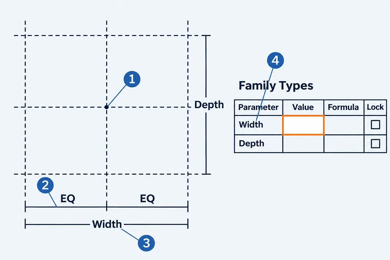
- Change Width and click Apply. Both side planes should move, with the origin halfway between them. Change Depth and check the front and back in the same way.
- Use New Type in Family Types to name a size. For a teaching example, use 600 mm Width and 400 mm Depth.
- Create a second type at 900 mm Width and 400 mm Depth. A new type copies the current type's values and formulas, so check both dimensions after creating it.
- Switch Type Name between the sizes and click Apply for each. Then try a different Depth value to check that dimension independently.
These dimensions are example geometry, not furniture specifications. If the wrong plane moves, inspect which references the dimension measures and which parameter labels it before drawing a solid.
5. Add an extrusion and constrain its edges
In the plan view, choose Create tab, Forms panel, Extrusion. Use the horizontal reference-level work plane for this block; if necessary, choose Create tab, Work Plane panel, Set before sketching. Draw a closed rectangular loop at the four outer reference planes.
Under Constraints on the Properties palette, set Extrusion Start to 0 and Extrusion End to 450 mm for this teaching example. The extrusion runs perpendicular to its sketch plane: this sets the block's height, while the plan's Depth parameter controls its front-to-back size.
- While editing the sketch, use Align. Select an outer reference plane, then the corresponding sketch line.
- When the lock symbol appears, click it to constrain the line to the reference plane. Repeat for the other outer edges.
- Choose Modify | Create Extrusion tab, Mode panel, Finish Edit Mode. Open a 3D view to inspect the solid.
- Return to Family Types and apply both types again. Change Depth too. Check that the solid follows the framework without gaps or constraint errors.
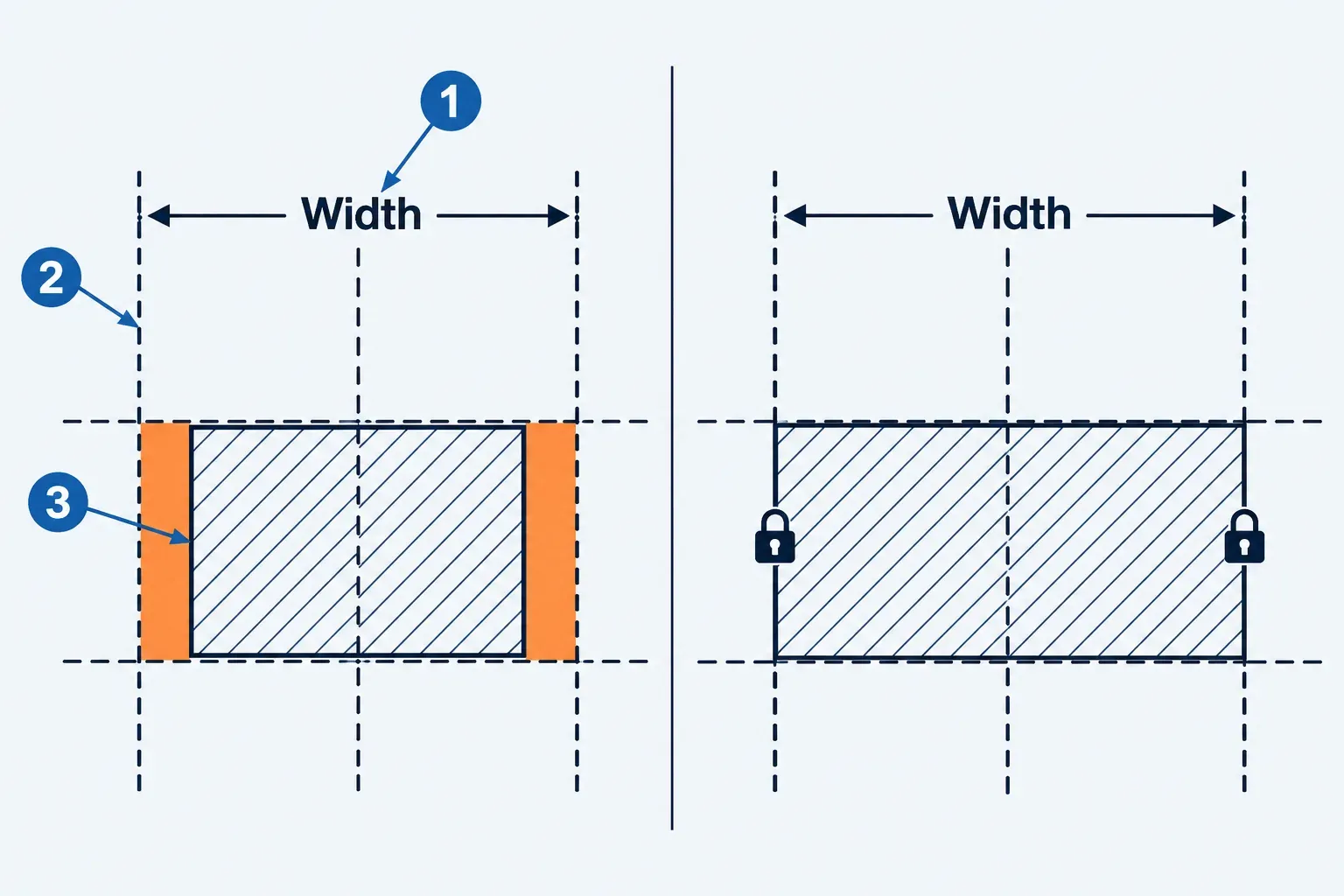
If an edge stays in place when Width changes, check the dimension's references and the sketch's alignment constraints before redrawing the family. Constrain the form to reference planes, lines or levels; constraints between pieces of geometry can behave unpredictably when parameters change.
6. Save, load and check the placed component
Save the RFA again so the working file contains the geometry you just added. Choose Create tab, Family Editor panel, Load into Project and select the receiving test project if several are open.
- In the test project, open a plan view and choose Architecture tab, Build panel, Place a Component. Select your first type in the Type Selector and click to place it. Place another instance using the second type.
- Select one instance and click Edit Type. Check Width and Depth in Type Properties, then compare the placed geometry in plan and elevation. These checks verify the ordinary family parameters used in this example.
- Follow Autodesk's family testing checks across plan, reflected ceiling plan, elevation, section and 3D, at Coarse, Medium and Fine detail. Apply each type and inspect its shape and placement.
- Check an unfiltered Furniture schedule that includes the family and type identification. Confirm that the new family is represented. This checks its category and inclusion; it doesn't make custom Width and Depth available as schedule fields.
- Load a furniture tag, then choose Annotate tab, Tag panel, Tag by Category and tag an instance. Check the field the tag is designed to show. Reporting custom dimensions needs the shared-parameter setup discussed above.
Only move the RFA into the shared library after its checks pass. The separate guide to loading the family into your project covers library loading and reload choices.
Add shelves, voids, materials and visibility rules one layer at a time, flexing again after each change. For an element that must respond to a wall host, continue with a sliding door family in the families section; its host thickness becomes another condition to test.